Menu:
Portland Reflector
Portland Reflector went out of business in July 2018.
The idea for the Portland Reflector started when I was at an event put on by the BTA (Bicycle Transportation Alliance). The BTA had a class on all-weather biking at the Portland Fix-it-Fair that I attended as I prepared to purchase my first bike since middle school. When the speakers discussed options for reflective clothing and equipment, they covered expensive bike specific jackets, orange safety vests, and reflective tape that could be attached to the bike or rider. I didn’t like any of these options; I already owned a perfectly good, but black, rain jacket. I didn't want to wear an orange safety vest. And putting reflective tape on my clothing sounded like a mess. I asked if there was a magnetic option, and the presenters said they hadn’t heard of one. Another person in the class said, “You should make that!”
At first I assumed a product like the one I had in mind must exist, but after searching, the closest thing I could find was the Claq magnetic reflector. This product uses a small figure eight shaped part, with a magnet on both ends that allow it to attach to a piece of clothing. Because both magnets are in the same piece of material, they can only be attached to the edge of a piece of clothing, rather than in the center. They also don't provide a very large surface area of reflective material. I wanted to create something that could be attached in the center of a jacket or backpack, and that would be much larger.
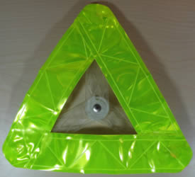
I purchased a roll of 3M reflective material, and cut three strips to form a triangle shape. The image below shows the first prototype I made to get an idea of the size. I placed a magnet on the inside of the sweatshirt and on the outside of the reflective material on each corner of the triangle.
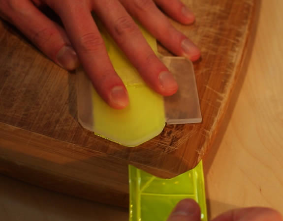
After I was happy with the size, I designed a stencil I could use to consistently cut each length of the triangle so the shape and size would be the same for each part. I printed the stencil on my Form 1 SLA 3D printer which I had recently purchased. The image below shows part of the stencil with a piece of reflective material that was cut with a hobby knife.
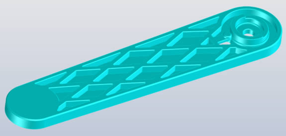
The reflective part of the product would have a magnet in between the layers of reflective material where they overlap at each corner. To hold the reflector in place, I decided to design a brace that would go on the inside of your clothing or equipment with matching magnets. I did some testing with various magnet sizes across different clothing thicknesses to determine how powerful the magnets needed to be. Once I was happy with the magnet size I designed the brace, which I would also 3D print. The image below shows one of the three arms of the brace.
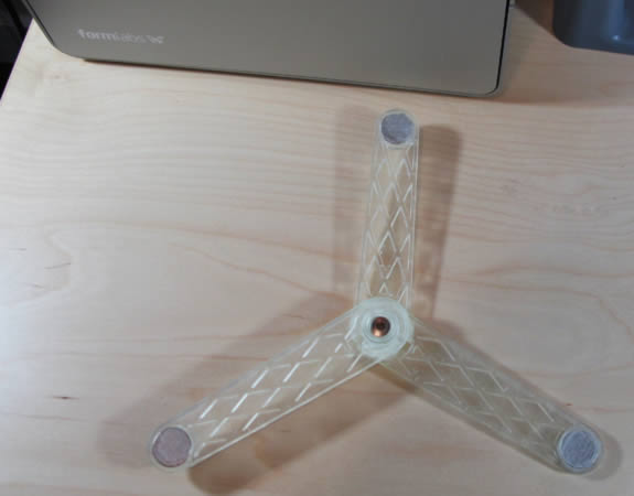
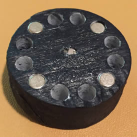
The brace would use three rotating arms that would line up with the magnets on the reflector when open, but could then close to save space when not in use. The brace was designed in a way that it could eventually be injection molded. It had features that would control the rotation angle and hold the arms in place when they were fully opened or closed. I planned to eventually design it in a way that everything would snap together and not require additional hardware, but for the prototype I used a press fit binding barrel and cap. The image below shows the first prototype of the brace with the magnets installed.
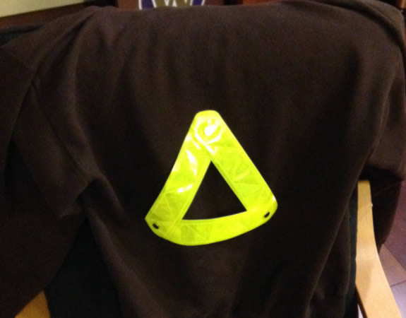
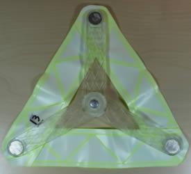
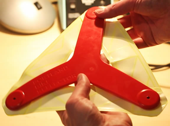
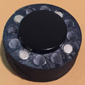
I spent some time testing different superglue types to find one that would work well for bonding the PVC reflective material. After settling on one I made my first prototype of the reflector part of the product with encapsulated magnets. The two images below show the front and back of the first finished brace and reflector prototype.
After finishing the first prototype, I decided to go for a bike ride to test it out. The rigid brace was very uncomfortable against my back on the inside of a t-shirt. After this test ride I decided the brace part had to be made from something flexible. There were also some issues with the features that controlled rotation on the brace. I believe part of this was because of how brittle the 3D printed material was. These issues would have needed some work if I had continued with the rigid brace.
At this stage I decided I wanted to turn this into a product that I could sell. Moving forward I started to think about ways I could make the prototypes in larger volumes for people to test. I designed a flexible part that would include overmolded magnets to act as the brace. The first design for this part is shown below.
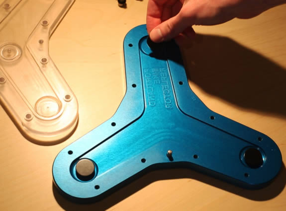
After designing the flexible brace, I used the design to create a two part mold I could use to make prototypes. The aluminum base of the mold had space for three thin cylinder magnets that would hold the overmolded magnets in place. There were also alignment features and threaded holes. The top of the mold would be made from clear polycarbonate so I could watch as the flexible material was being injected. I put an injection port in the center, as well as at the end of each arm. These would also be used as vents. The finished mold is shown below with magnets being placed on each cylinder magnet.
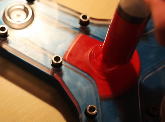
I ordered a bunch of different two part silicones and urethanes to find the right stiffness for the brace. I started by testing the silicones, but eventually abandoned them for the prototypes because they were all very viscous and difficult to inject before they started to harden. I ended up switching to a two part urethane from Smooth-On with a hardness of Shore 80A. This material was a lot easier to mix and inject, and also came in a translucent color that allowed me to add different pigments to color the braces. During this process I learned that I needed to spray mold release on both sides of the mold before injecting the silicone or urethane. During the first few tests I almost ruined one of the molds because the urethane was sticking to the aluminum and polycarbonate. The image below shows one of the molds being injected with urethane containing red pigment.
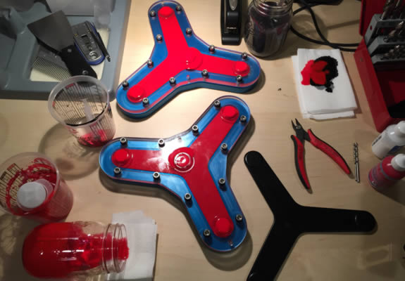
Using the new molds I was able to make six to eight braces per day. I found they could be demolded after about four hours in the mold. The image below shows two red braces curing in the molds, with a finished black one next to them.
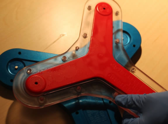
The image below shows a red brace being taken out of the mold. What looks like water droplets is the mold release.
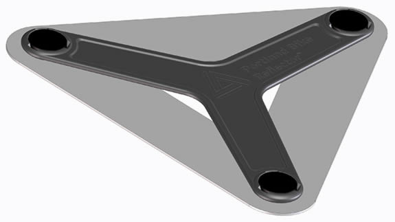
The image below shows a finished brace on the back of a reflector.
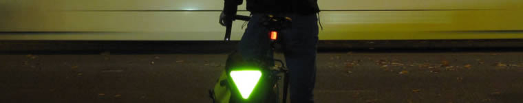
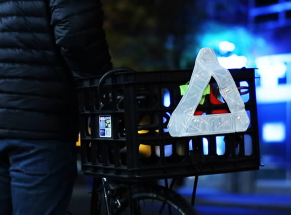
This new brace design was a lot more comfortable to wear. It was still noticeable underneath a t-shirt, but not uncomfortable. I made a bunch of this version of the prototype and started handing them out to friends and coworkers to test. The image below shows one of the finished reflector prototypes attached to the basked on the back of a bike.
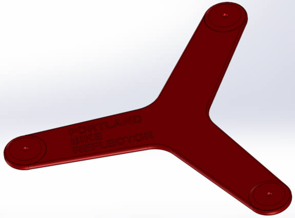
As I continued to move forward with this project, I decided to have a logo made. I got in touch with Lily Donovan-Seid, who designed the logo for Shockmetrics. She create several options for the logo, and I ended up selecting the one in the image below (the one below is the final version, it originally said "Portland Bike Reflector" which is what I was calling the project at the time).

Now that I had a brace that I thought was close to the production design, I started looking into how I would manufacture the reflector part. I spent a while looking into how I could bond the strips of reflective material using something other than superglue. I was also looking into manufacturers with cheaper material than 3M to bring the cost down. I ordered samples of reflective material from eight manufacturers in China. After doing some testing with the material samples, I started talking to one of the manufacturers to see if they would be able to bond the strips with the magnets in between them. They were confused about why I wanted to bond a product that is normally sewn onto clothing, and asked what my final product would look like. When I showed them the full triangle design, they told me they would be able to stamp the design out from a single piece of material and RF (radio frequency) weld the different layers that make up the reflective material together with the magnets inside.
During this time I had also been looking into magnet suppliers. I ordered samples from two different companies, and then went with the cheapest one. I didn't notice any difference in quality or strength between the two.
I came up with a simple design that included the logo and sent it to the Chinese manufacturer. The image below is a picture of the RF die they made to create the reflector.
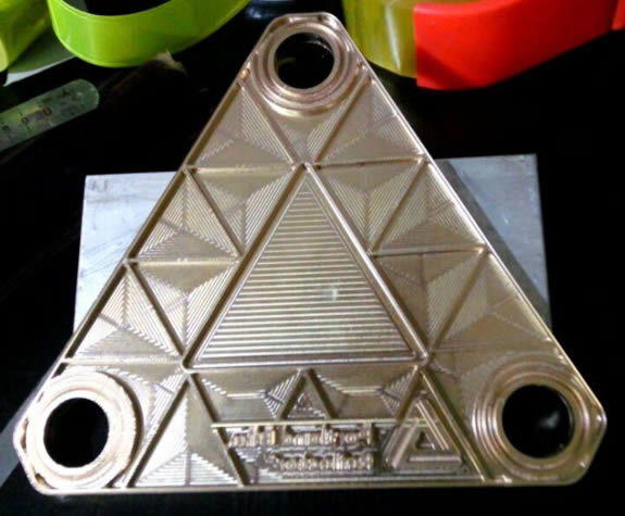
I placed several circular bond lines around the magnets to prevent a tear from propagating from the outside in. I also separated the rest of the design into multiple smaller triangles, that way if one is punctured and fills with moisture the rest of the reflective material will continue to function.
After the die was made I had magnets sent from my magnet supplier to the reflector manufacturer and placed an order for 10 reflectors to see how they would turn out. After receiving the first 10 and being happy with them, I ordered an additional 65 for testing. The image below shows some of the reflectors I received.
Overall the Chinese reflectors turned out a lot better than the ones I had been making with reflective strips and superglue. However there were some issues. It was fairly common to have small puncture holes on the back side of the reflectors. I also noticed these holes in the rolls of reflective material they had sent, so I'm not sure if it was a common defect caused by the equipment they use to make the raw material, or something else. Another issue was the color from the reflective material would leach onto the white PVC backing of another reflector if they were stacked, which created a stain.
While the design I created worked fine for testing, I wasn't happy with it for a product I would try to sell. Since I also wasn't happy with their quality, I decided to have the graphic designer that made the logo come up with some concepts for what the reflector might look like, and then try to find a new manufacturer. She again came up with a few different designs, and I selected the one below.
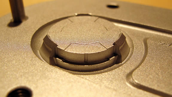
In order to get the weld circles as close as possible to the magnets so they wouldn't slide around too much, I came up with a method to help center the magnets. The images below show the concept without the reflector magnet on the left, and with it on the right.
The concept uses a cylinder magnet in the center of the black 3D printed part to attract the reflector magnet, and the other four cylinder magnets oppose it. Since the four opposing magnets are set just outside the diameter of the reflector magnet, they help push the magnet toward the center, which does a better job of centering the magnet than if there was only the single cylinder magnet in the center. Once I found a supplier in the US I shared this design with them so they could incorporate it.
When I had been looking into RF welding in the US before I started talking to the Chinese manufacturer, I had been sent a sample of some welded reflective material. It was made by a company called ORAFOL and seemed a little brighter than the 3M material I had been using originally. I got in touch with one of their sales representatives about making a custom part. They said they don't do custom parts like what I wanted to make, but put me in touch with a manufacturer that uses their materials.
After speaking with this new US based manufacturer, Fey Industries, I decided to have them make the new design. The first two samples they sent me are shown below.
For the new design I decided to make the corners round, and I also added a new reflector in the center. The center part, which would have been scrap material, would now be a separate reflector. The same type of tear seal that creates the main reflector would form the smaller one. The two rectangles in the center of it would also be formed by tear seals to create features that a strap could be fed through, allowing the reflector to be attached to a backpack or pannier strap.
Since I was switching to a US manufacturer for the reflectors, I decided to also look into a US supplier for the magnets. It turned out the last US mine for neodymium material had recently closed, so having the product made 100% in the US wasn't an option, so I continued to use the Chinese supplier.
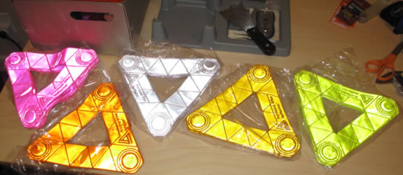
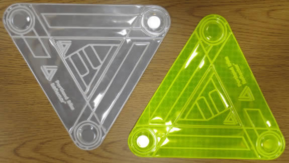
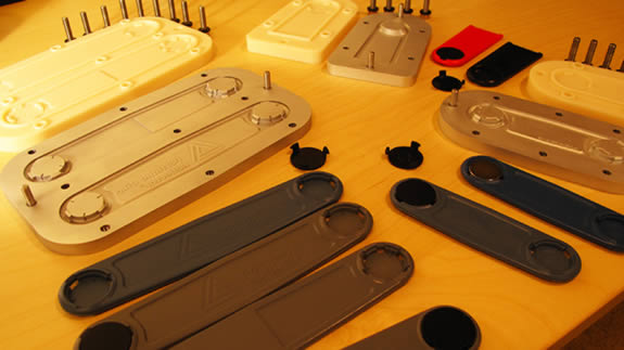
After receiving these new samples and being very happy with them, I ordered 90 reflectors to start testing. The image below shows the four colors I ordered. The top is with normal lighting, and the bottom is with a camera flash in the dark.

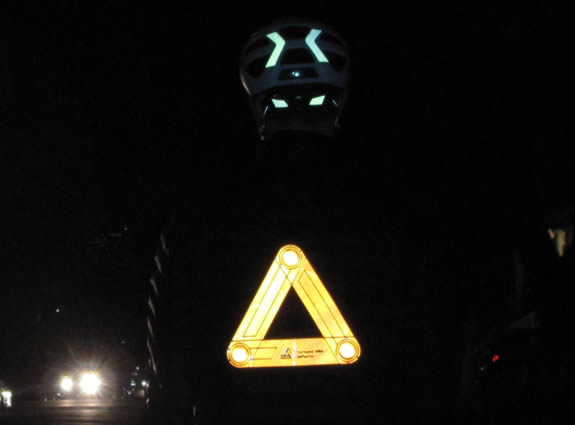
The image below shows an orange reflector attached to the back of a jacket.
Now that I had a way to manufacture the reflectors, I started looking into how I would make the brace in larger quantities. I got in touch with R&D Plastics, a local injection molding company, to talk about the design. There were a few changes that would need to be made to keep the magnets in place, but overall it looked like the design would work.
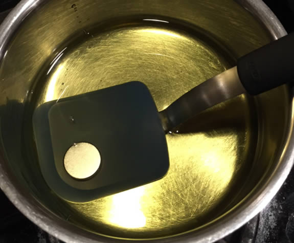
Then after a little more research I realized I might have a problem. It turned out the molding temperature would be a little higher than the point where neodymium magnets start to lose their magnetism. To test this I decided to heat up avocado oil in my oven to the molding temperature, and then place a magnet in the oil for the same amount of time it would see those high temperatures in the mold. I checked the strength of the magnet before and after, and there was a noticeable drop. The image below shows the magnet in the oil.
While I ran my test with the worst case conditions for time and temperature, I decided it would be too risky to move ahead assuming this would work. There are ways to remagnetize the magnets after they are in the final product, but at the quantities I was assuming for an initial run, it would have added way too much cost. So I had to come up with another option.
I decided the way I would get around this problem was by molding the flexible part of the brace with an opening for the magnets, and then use a snap in rigid cap to secure the magnets. My first test of the snap design is shown below.
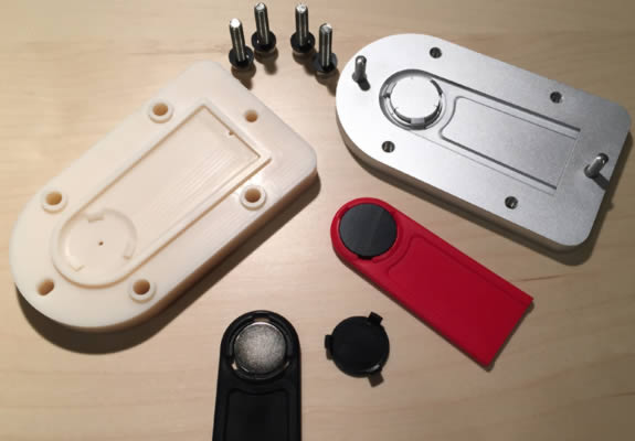
I made a mini mold to create the end of one of the brace arms. I also used this opportunity to test a thinner arm with a stiffer material to get the same overall stiffness. The image above shows the two sides of the mold, a red sample with the magnet cap in place, and a black sample with the magnet in place and the cap next to it. The design went together as expected, but the cap was a little too easy to remove. I wanted it to be as secure as possible so the magnets wouldn't come out accidentally.
I decided to do a few more iterations for this concept to get it right. The image below shows the final design of seven that I tested. There are compression feature to keep the magnet from rattling, as well as much large snap holes. The cap part for this design adds features on the side of each snap that act like a fish hook, so once the snap is in place, it will dig into the urethane if you try to remove the snap. I was satisfied with how this design performed and started talking to the injection molder again about making the two parts.
The image below shows all seven of the designs in three different molds that were used to test the new concept to hold the magnets in place.
The image below shows the finished concept for the brace with the reflector attached on the back. This design includes the final snap in cap design, a thinner brace, and the logo in the center.
Now that I had everything pretty much ready for manufacturing, it was time to put the project on Kickstarter.
Early on I decided I would use Kickstarter to try to fund the project. Most of the money raised would be used to purchase the injection molds. After I had finished making a bunch of the early prototypes, I hired a couple people to film, got a few friends together, and went out to get some footage for the Kickstarter video. The finished video, edited by my brother-in-law Jordan Doig, is below.
Unfortunately the Kickstarter wasn't successful. I think there were a few things that went wrong. I didn't do a good enough job of promoting the project, the price was too high, and I think some people were confused about how the product was meant to be used.
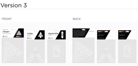
Based on some feedback I had received, I decided to design a new reflector that would be a little smaller, cheaper to manufacture, and also wouldn't require any injection molded parts. This new design had been an idea for a follow-on product while I was working on the original, but because of the interest I received in a smaller cheaper product, I decided I should move forward with this design and self fund it. I again contacted Lily about coming up with the look for the product, which is shown below.
The reason this new product doesn't require any injection molded parts is because each package would come with two of the magnetic reflectors. Since the product is smaller and only uses one magnet, it wouldn't require a brace part to hold the overall shape. I ended up making four different colors of the reflector (yellow, orange, pink, and blue), as well as silver. Each package comes with one of the four colors, and one silver. The user can decided to have the colored reflector or the slightly brighter silver reflector on the outside of their clothing or equipment, with the other reflector on the inside holding everything in place.
I also decided to make new versions of the strap reflector. The new designs would be standalone products, rather than waste material. I ended up with two different designs for the magnetic reflectors, and four designs for strap reflectors. Two of the designs for the strap reflectors are shown below.
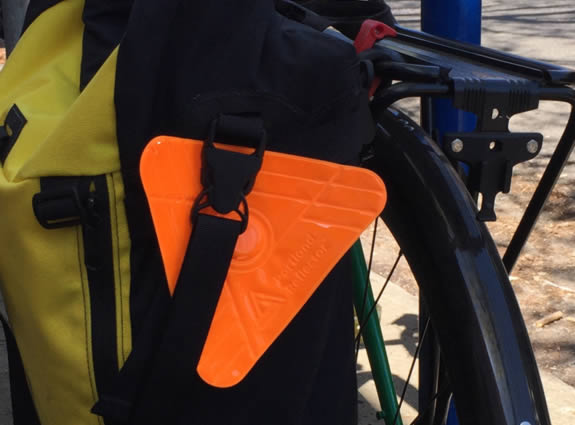
Once the designs were finished I had the same company that had made the final version of the original design make the new products. I decided to start by ordering one of the magnetic versions, and two of the strap versions. Once the dies were made, I had a few samples of each product sent to me. Unfortunately on the magnetic reflector, I had designed the weld around the magnet a little too close to the magnet, and there were some tears caused when they welded it all together, so I had to order a new die for that product. The second set of samples looked great, so I placed an order for a large quantity of reflectors. An orange version of the magnetic reflector is shown below attached to the pannier on my bike.
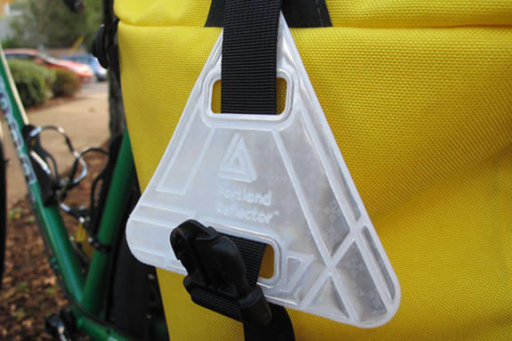
The image below shows a silver strap reflector also attached to the pannier, through one of its buckle straps.
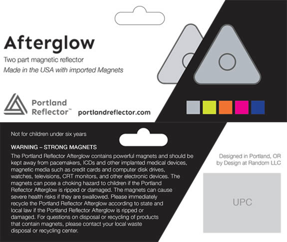
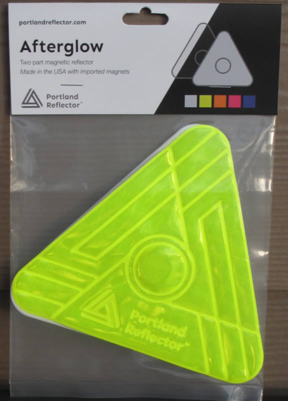
For packaging I decided I would use poly bags with header cards stapled to them because this is a fairly inexpensive way to package a product. I ended up selecting fairly thick bags and header cards so the magnetic attraction between products wouldn't tear the header cards off as easily. Lily came up with a few options for the packaging design, and the one I chose is shown below.
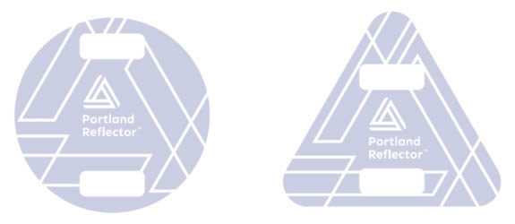
I wanted the header cards to give all of the normal information about the product, like name, brand, website, logo, etc. But I also wanted it to show how the product is used. Lily came up with some great ways to show this. The package design for the magnetic reflector shows two of them, with the black division acting as the material the magnets would be connected across. And the packaging for the strap reflectors shows a white strap going through each reflector. The full front and back of the header card for the magnetic reflector is shown below.
The finished magnetic reflector inside its packaging is shown below.
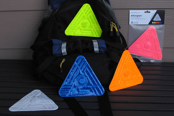
The image below shows all of the colors, along with silver.
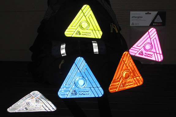
And the following image shows the reflectors illuminated at night.
Once I had received all of the reflectors and packaging material, I started to package them. I quickly realized how difficult it would be to consistently align the header cards with the bags and place the staples in the same location each time. I came up with a very cheap and simple way to solve this.
I bought two staplers and a small bag of Legos, then I placed the product bags and staplers on top of some scrap acrylic I had, and used the Legos to keep everything in the same position. Legos were placed around the staplers to keep them from moving, and the rest of the Legos were placed around the perimeter of the different sized bags and header cards. The image below shows the final setup.
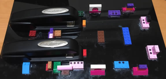
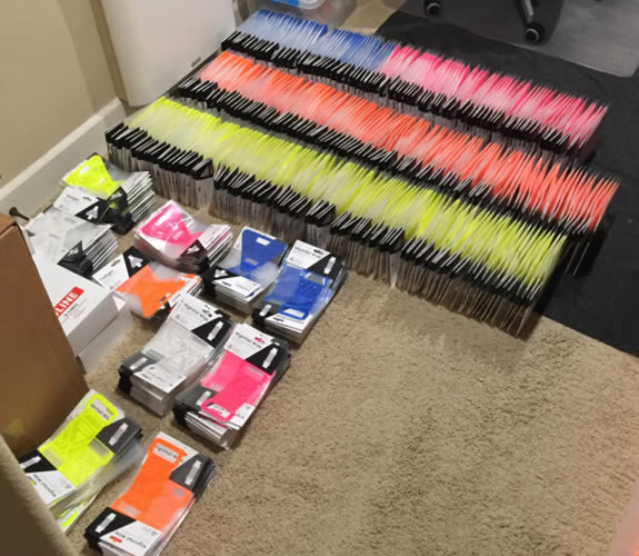
The black Sharpie dots on some of the Legos show where certain parts go for the different bag lengths and widths for the three different products. After several long nights using this setup I finally had everything packaged and ready for sale. The image below shows some of the inventory.
As I had been finalizing the design and ordering all of the reflectors, I had also been getting things ready to start selling. I created an online store, started to post more on social media, ordered the supplies I would need to ship the reflectors, and figured out how to print the shipping labels at home to speed things up.
About four months after the Kickstarter failed, I started selling the new reflectors online. I started by sending an email to everyone who had backed the Kickstarter campaign, and then started reaching out to local bike shops, as well as bike bloggers to see if they would be interested in testing and reviewing the product.
I ended up getting about a half dozen reviews, as well as several other mentions by bloggers. I also had the product in three stores.
After a little over a year, the product was selling okay, but not well enough to be worth my time. Then in July 2018 I received a cease and desist letter from a company in a similar space, and it turns out my logo was very similar to theirs. Since I was already losing interest in the project I decided to shut it down rather than rebrand and order all new product.
Toward the end of this project I learned that I have no interest in marketing or selling a product. The creation and development parts are what I enjoy, so I think I'm going to stick to that.
In November 2019 I sold the Portland Reflector website domain to FLECTR, another company that makes reflective products for biking. They were just about to launch a Kickstarter campaign for a similar magnetic reflector, along with a couple other products.
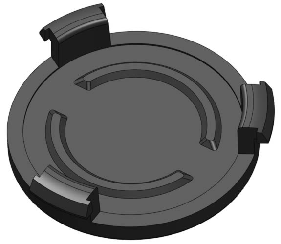
A few years after the project ended, I decided it would be fun to 3D print the original brace design from my Kickstarter campaign. I had to redesign some features to make it easier to 3D print, for example, reducing the need for supports in some areas. I also had to modify the snap features for the caps that hold the magnets in place. I had to reduce the snap interference because the 3D printed caps weren't as strong as a machined or molded part, and they would break easily if there was too much interference. The finished design for 3D printing is shown below.

The cap, with reduced overhang and smaller fish hook features compared to my original design, is shown below.
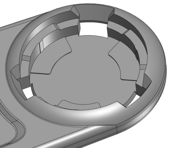
The part of the brace that holds the magnets is shown below. There are lead-in features for the snap fits on the caps.
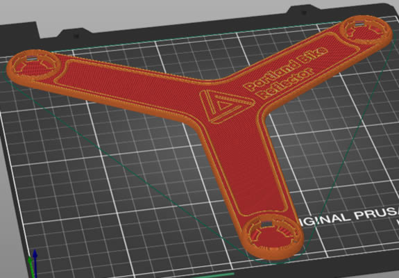
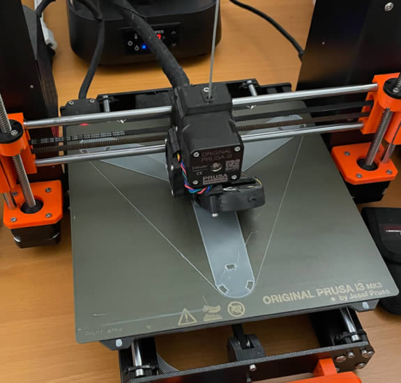
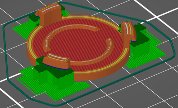
By complete luck the brace just barely fit on the build platform of my Prusa i3 MK3S printer, with only a few millimeters to spare. The file that would be printed in 85A thermoplastic polyurethane (TPU) is shown below. I was able to print this part with supports turned off.
The image below shows the brace as it was being printed.
I tried a few different materials for the caps but ended up going with nylon. When I tried using PETG and a PC blend, the snaps broke off way too easily. The layer to layer bonding with nylon was much better, but because of that it also meant there were a lot of modifications to the support settings. Otherwise the supports were extremely difficult to remove from the part. The cap file that was printed is shown below.
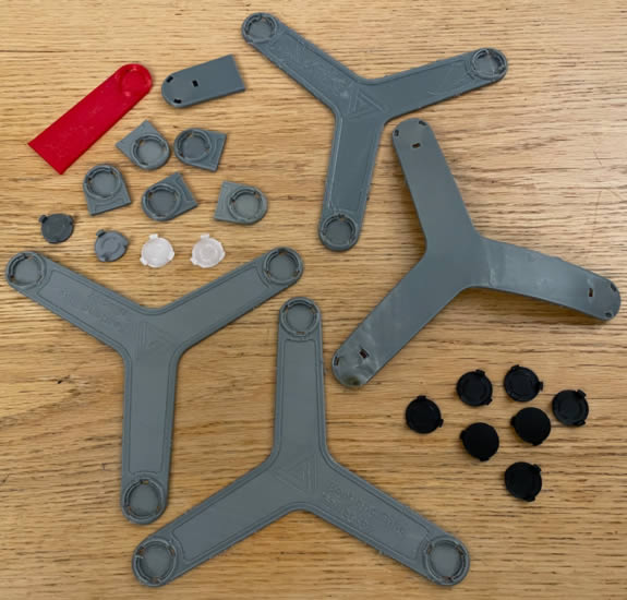
There were quite a few test prints to make the brace. I started with different designs for the snap interference, and testing different materials. These are shown in the image below in the upper left. The two full brace parts in the upper right were ones that did not turn out well. The first because the extrusion multiplier was set too high for the TPU, and there were excess globs of material all over the print. The second bonded to the build platform way too well and damaged the platform and part when it was removed. Lowering the bed temperature solved this problem. The braces in the lower left were both successful. And the lower right shows a bunch of nylon caps.
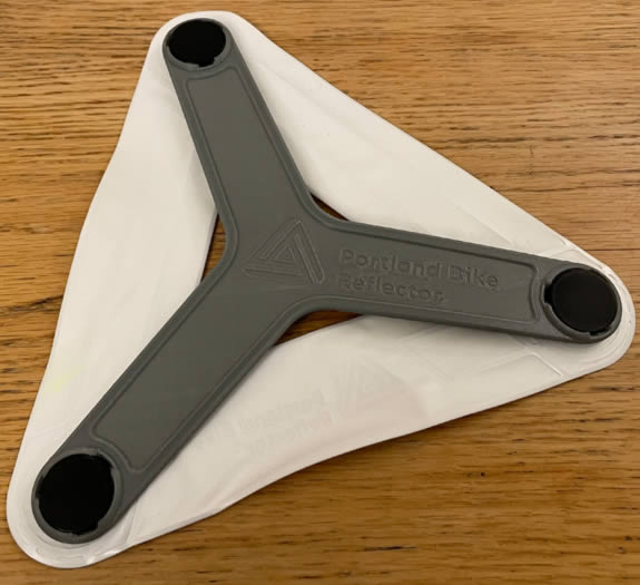
The final printed brace connected to one of the original reflectors is shown below.
Page created: 2018