
Menu:
Lathe
The main project for ME 355 (Introduction to Manufacturing Processes) was to machine the parts to create a mini lathe. Teams of three were formed with each team responsible for a different part of the lathe; my team chose the tool holder. The design we were given was a very basic tool holder that could not be adjusted for height to account for inaccuracies in other parts. We decided to redesign the part so the height could be easily adjusted. Two images of the new design from SolidWorks are shown below.
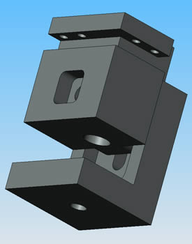
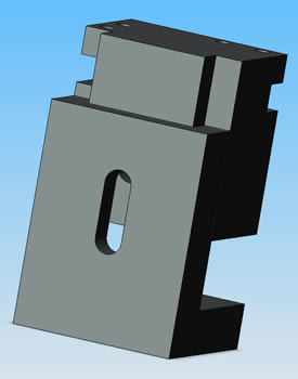
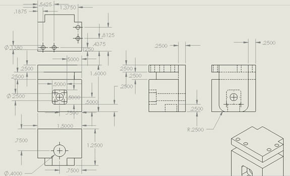
The hole in the bottom of the base is where the tool holder attaches to the lathe; the hole in the bottom of the slider is there so the bolt will not interfere with the slider movement. The front indent is for a T-nut to secure the slider to the base. During the design of this project our team had to keep in mind the limitations of the manufacturing process we were using. For example, the T-nut had to have rounded edges because it would not be possible to create sharp corners on this type of cut with a circular end mill. The oval hole on the back gives the slider a travel distance of 0.5 inches. The part was designed to meet the height specification at the center of travel so we could account for an inaccuracy of +/- 0.25 inches. The following two images show the drawing files that were created for the base and slider respectively, in order to machine each part.
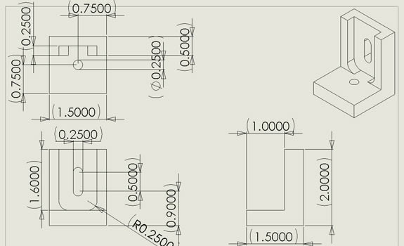
The holes drilled in the top of the slider are there to hold the tool oriented in either the x or y direction. Each hole was tapped to allow screws to be inserted to secure the tool. The images below show two views of the assembled parts at their lowest and highest level of travel.
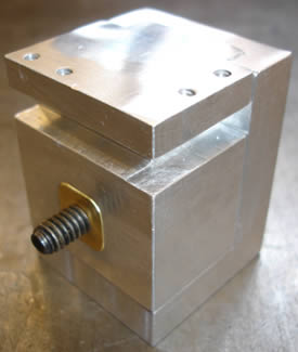
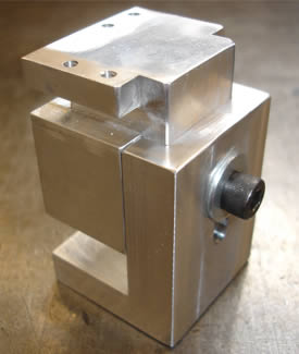
The base and slider were machined from aluminum using a 3-axis mill (2-axis CNC). The T-nut was machined from brass.
Team members: Jacob Hiester, Ryan Johnson
Page created: 2010